

This post has been adapted verbatim from a paper accepted presented during International Conference on Computer Security in a Nuclear World: Expert Discussion and Exchange titled ‘Building and Breaking the Protection Provided by an Optical Data Diode Using Spare Parts’ authored by myself Daniel Gleeson, and Ben Donovan.
Abstract
This paper presents an overview of the construction and implementation of unidirectional networking through an optical fibre data diode while demonstrating post-implementation issues that need to be addressed to ensure the desired protection is provided. This particular topic was chosen due to its relevance for nuclear facility operators. Nuclear Security Series 17 highly encourages no inwards data flow of any kind to Level 1 systems. Technical solutions are provided on implementing select applications that require stateful network protocols over the constructed unidirectional link. The paper stresses that there are further issues around implementing a data diode that are shared with both entirely connected and disconnected networks. Where a lack of a robust security culture on the more protected segment can lead to a compromise of the additional integrity protection that the data diode provides. Throughout detail is provided that is accessible and easily understandable to various skill levels in networking, programming, and control system design; empowering operators and practitioners with a greater understanding of the optical diode technology and its implementation. The design of the optical fibre diode, the software created in overcoming the requirement for stateful networking, and details of a covert device allowing foreign input will all be provided as technical resources. Where possible physical components are constructed with spare parts that would likely be found in a converged Industrial Control and Information Technology environment.
1. Introduction
When there are two networks or devices that require different levels of protection employing a security risk management perspective they would be entirely disconnected forming what is termed as an “air gap”.
A unidirectional link describes a network link that allows data to flow between two devices in only a single direction. Techniques for unidirectional networking can be seen in terrestrial broadcast television and satellite downlinks where the communications infrastructure is only capable of passing data in a single direction 1. When a unidirectional link is implemented as part of a security gateway between two systems of differing protection requirements a demonstrable one way connection can be achieved. This is an enabling mechanism to allow data to flow in a single direction while still providing an effective air gap for the other direction of data flow across the link.
A modern unidirectional link termed a “Data Diode” implemented through optical fibre first originated in two 1999 technical reports published by Australia’s Defence Science and Technology Organisation (DSTO) entitled “Data Diodes” 2 and “Implications of an Optical Data Diode” 3. The DSTO papers outline two modes of operation for a data diode that depend on the inherent risks to the systems, processes, and information on the more secure side. Where confidentiality is the primary concern a link can be created to allow data to flow into the more secure network while preventing exfiltration of any information that resides within. Typically employed to separate systems of differing security classification this allows a strict implementation of the Bell-Lapadula model for access control (no read-up, no write-down)4. Alternatively in a mode where Integrity or Availability make up the key risks to a network the unidirectional link is configured in such a way that data is allowed to only flow out of the more secured system. This can then be considered an implementation of the Biba Integrity Model (no write-up, no read-down)5. Of the two the Integrity mode is the most relevant to critical infrastructure. This is supported by the IAEA through NSS 17’s suggestion for Level 1 systems to have no networked data flow of any kind from weaker security levels6.
2. Purpose
The Australian Nuclear Science and Technology Organisation (ANSTO) separates it’s Reactor Control and Management System (RCMS) for the Open Pool Australian Lightwater (OPAL) research reactor from a network housing the detectors and computing infrastructure for the attached Neutron Beam Instrument Facility. Experiments undertaken on these beamlines require data from the RCMS to offset their calculations while the RCMS is a Nuclear Safety contributing system and therefore has inbound data flow restrictions. To address this during commissioning of the reactor, a gateway was created between the two networks to achieve unidirectional networking through a high assurance optical fibre data diode.
During a recent upgrade project a requirement to engineer an equivalent setup for a lab environment emerged to assist in the development a new transfer mechanism. It was broken down into three phases: construction of the diode following the principles outlined in the DSTO paper, development of software to proxy information across the diode, and a smaller side project to demonstrate a credible security threat to the RCMS.
3. Building a Unidirectional Link
It is possible to create a unidirectional link across any medium that separates the cable medium for transmission and receipt of data. This approach can be applied to Ethernet running over twisted pair cabling up to a standard of 100BASE-TX, later standards have moved to a technology that transmits and receives on all pairs simultaneously. When implementing such a link it is important to sever every cable besides the desired transmit pair as any remaining connection could covertly be used to subvert the provided protection via a return return path.
There is also a major disadvantage with this approach, in an off the shelf network card the pins in physical transceiver are not necessarily exclusive to a transmit or receive function and there is no way of visually inspecting this. The transceiver can determine which cable pairs are assigned to transmit and receive before the media access controller, this is observable through the application of Auto Medium Dependent Interface Crossover (Auto MDI-X) in modern network interfaces.
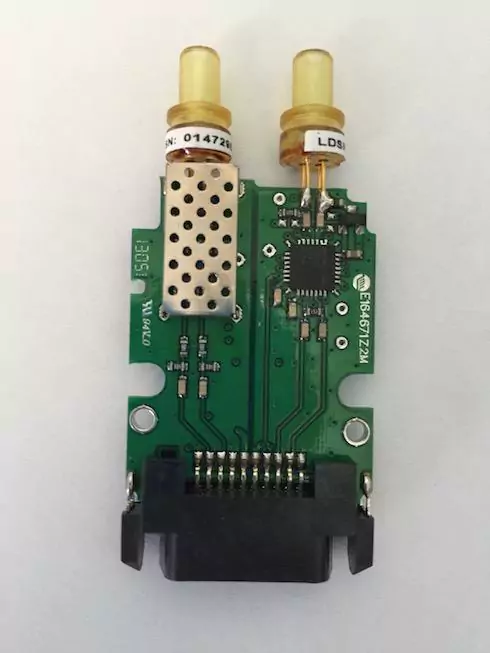 FIG. 1. PCB of a GBIC
Transceivers used in two-cable optical fibre networking on the other hand do not carry this disadvantage. Taking apart a pluggable transceiver shows an observable visual distinction between the modulator and light source on the transmit side and the photo sensor and demodulator on the receive side. Both channels are then able to pass traffic, independently across separate cables utilising dedicated, physically isolated circuitry, where FIG. 1. shows a clear electrical separation on the circuit board between onboard transmit and receiving functions.
Building on this an optical data diode is constructed by removing one of the fibre cables between a pair of transceivers. The remaining cable depends on the chosen protection model, for integrity or availability the transmit on the more protected segment’s interface will be connected to the receive on the destination less protected segment’s interface. Whichever side hosts the transmit role in the optical diode needs the receive side cabled to a the transmit of another powered transceiver so a carrier signal is received, a requirement before the link will be considered up and transmission to the other side of the diode can occur. This additional transceiver should be physically located on or powered by a chassis on the transmission side of the diode to avoid the potential of creating a secondary channel and breaking the provided protection. This model also ensures the absence of data being transmitted across the carrier signal providing interface by maintaining the integrity of an entire data path.
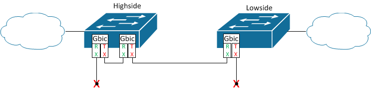 FIG. 2. Logical network interconnection topology
Rather than a direct connection between two servers with fibre network interface cards the diode was built between existing lab networking equipment as exhibited in FIG. 2. This model employed, while providing an equivalent level of protection, also allowed utilisation of a dedicated and flexible networking stack independent of the sending and receiving systems. While not a true security gateway this flexibility allowed the development and testing of multiple approaches to achieving the desired unidirectional networking simultaneously.
Each side of the data diode was configured as an interface on subnets respectively representing the transmitting and receiving networks split by the implementation of the diode. There were a number of networking technologies supported by the hardware that needed to be configured in a specific manner to ensure full support for caveats of implementing a data diode.
- Modern fibre interfaces support speed negotiation. Due to the nature of the diode preventing bidirectional communication this negotiation will fail to complete. While speed negotiation is enabled and not complete the link is unable to become active. Therefore to implement the diode speed negotiation needed to be disabled.
- The particular hardware used supported a feature called unidirectional link detection designed to shut interfaces where a unidirectional link is detected in order to prevent looping. As a diode is by definition a unidirectional link this protocol requires disabling.
- Static Address Resolution Protocol (ARP) entries were created on the protected transmitting segment so communication could be appropriately directed to devices on the less protected receiving segment.
4. Transfer Across a Data Diode
To understand the communication across the data diode will be achieved it is best to reference the OSI model. This model splits the communication up into seven encapsulated layers which each facilitate part of the communication. As a transmission occurs it passes from the sender’s application layer down to physical where transmission occurs. The transmission then reaches the receiver and progresses back up the layers.
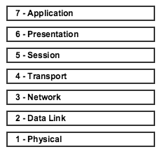 FIG. 3. The OSI model showing conceptual stages within the data transfer process.
Within a standard network, state is typically maintained within a protocol such as the Transmission Control Protocol (TCP). TCP is able to achieve a highly reliable transmission through techniques such as SYN/ACK numbering and sliding windows, operates on the transport layer, and underpins most common protocols operating at higher OSI layers. Due to the nature of the data diode, stateful protocols are impossible to implement. The receiver isn’t able to acknowledge receipt of data or complete a handshake to initiate communication.
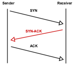 FIG. 4. The TCP handshake, demonstrating required bidirectional communication in a TCP session.
Another transport protocol, User Datagram Protocol (UDP) is capable of working over this type of link as it is unidirectional and stateless, it has no handshake requirement to start transmission and doesn’t acknowledge receipt of data. This however means it provides no solid guarantees to the successful transfer and ordering of data. There are limited options available on each endpoint as each must execute in isolation. UDP’s primitive environment for transmission shouldn’t be entirely relied upon and on its own it should be assumed unreliable.
One approach to increasing reliability is by implementing extra functionality within another layer of the OSI stack, typically the Application layer. Not all techniques are achievable given the unidirectional link however even implementing basic sequence numbering helps to reconstruct data, detect errors and track communication. A common technique is to include a checksum with the transfer, which can detect errors and trigger a retransmission. Due to the unidirectional link there is an inability to request retransmissions so this gives us no greater reliability. Instead implementing Erasure coding techniques such as Reed Solomon can provide the desired functionality7. This technology allows detection and most importantly, correction of certain data errors without requiring a retransmission. While this can dramatically improve reliability, the system still has to be viewed as a “best-effort” transfer.
Netcat was initially investigated as an easy way to implement communications between hosts. It already includes some of the functionality required such as send / receive mode and protocol selection. Netcat however was missing key requirements such as datagram sequencing and transfer termination which we would’ve had to implement in another application sitting behind it. It was decided that bundling the sequencing, erasure coding and other plugins into the application would provide more fine grained control over the transfer.
The Trivial File Transfer Protocol (TFTP)8 already includes this sequencing and is seen as a clear and configurable platform to build with. Many implementations are available online written in high level languages which make it easy to extend for this particular use case. TFTP still utilises bidirectional communication to provide an acknowledgement mechanism as transmission occurs during session creation and periodically as a lock-step mechanism to ensure each packet is transferred correctly. Both of these responses can be engineered out and are not required for a successful data transfer apart from one small issue. The initial response by the receiver specifies an ephemeral data port for the transfer to be directed to. Instead in the unidirectional implementation the requirement for this response has been removed. The sender is considered to control the state of a set of ports that are reserved on the receiver and specifies the port it intends to use by declaring it as the source port in the initial UDP packet that contains the write request. To facilitate adding modules to process arbitrary protocols a syntax for the filename field in TFTP has been defined that can trigger the receiver to forward the traffic to a registered plugin.
5. Breaking the Protection
Before attempting to break the protection provided by the data diode it was important to first consider what we aim to achieve, for a diode operating in a confidentiality-protecting mode this would be the exfiltration of data from the protected segment. An integrity protecting diode is different; here the focus is on preventing foreign input from entering a system.
With such an input channel a capable malicious adversary could compromise the integrity assurance of the network that the diode provides to the risk management process. Such a channel would require a device of some sort that is able to provide remote input onto the protected network. In designing such a device sample routine engineering processes were considered and analysed in order to identify a potential vector for compromise that highlighted the idea that peripheral devices will be introduced to Level 1 and 2 systems throughout their lifetime. Each introduction of a peripheral device carries with it a risk. Take the case of USB storage devices which are credited with the spread of the Stuxnet worm to isolated networks resulting in a vendor issued advisory notice recommending customers avoid their use9 10. Most operating systems allow device restriction policies to be put in place to block entire classes of unwanted device types11 12 13. There is however one class that is almost universally whitelisted, the Human Interface Device (HID).
The parts used in the device are a commodity USB-based microcontroller development board, a few jumper wires, GSM phone module, an internal USB cable destructively salvaged from an old computer chassis, and a few spare micro-USB cables. Each part had been acquired by ANSTO through it’s normal business activities or for other purposes. In particular the USB development board, a Teensy 3.1 14 had been purchased by ANSTO previously for a security awareness exercise and the GSM module, an Adafruit FONA 15 for evaluating its use as part of an SMS alerting system. The theory of operation behind the device is it would use a spare USB header in place on a workstation or server mainboard and be entirely concealed inside the chassis. For the device to be introduced covertly a scenario where a compromised supply chain allowed a malicious adversary to intercept the delivery of a pre-built chassis to a facility was conceived. Further due to an insufficient security culture the chassis would be considered trusted by the facility and configured in such that is was operating with a permanently active login session.
TABLE I: CONNECTING THE TEENSY AND FONA
| FONA PIN | Teensy PIN |
|---|---|
| VIO | 3.3V |
| TX | Pin0 |
| RX | Pin1 |
| Key | GND |
| RST | Pin4 |
| GND | AGND |
The Teensy was connected to the FONA using the onboard UART at 3.3V TTL level with the cable configuration as shown in TABLE I. After cabling all configuration was done on the Teensy through the Arduino IDE. While directly interfacing with the SIM800 chip on the FONA is possible 16 Adafruit maintains a library that provides a helpful level of abstraction 17. In the setup phase the teensy creates the serial connection between itself and the FONA and does some initial checks to ensure that an IMEI can be read from a SIM card indicating there is indeed a SIM card present. An optional define macro taking a PIN code for the SIM card as a string allows the teensy to unlock the SIM prior to entering the loop phase. For ease of use at the end of the setup phase assuming setup has been completed successfully the Teensy will activate a LED to show the logic has progressed to the main loop.
Within the loop the Teensy continually polls the FONA for the arrival of new SMS messages and processes them through a parsing function. The message is then deleted and the program goes into a delay before entering the execution loop again. In order for the device to be successful in introducing advanced exploits an interpreter was written for Duckyscript the scripting language from the USB Rubber Ducky project, an established HID penetration testing platform 18. Duckyscript allows complex combinations of keyboard commands to be sent to the host system and has a suite of existing payloads 19 and tools that are fully supported by the interpreter. In addition to fully realise the capabilities of the Teensy a number of extended commands have been developed to allow control of all mouse input functions.
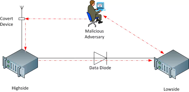 FIG. 5. An adversary with bidirectional communication across a data diode
The realised scenario is shown in FIG. 5. where a malicious adversary is able to use the proposed covert device to introduce foreign input onto the highside network therefore compromising it’s integrity. An advanced adversary that has also initiated a full compromise of the less protected lowside system could use the proposed device as an input channel into the network and then after a persistent attack would be able to achieve full bidirectional communication by exploiting the data diode itself as an output channel. While this is an additional capability allowed by the output channel provided by the data diode the same vector behind compromising the integrity of the more protected segment, the introduction of foreign input would apply to completely air gapped systems.
6. Conclusion
An optical fibre data diode is a provably secure device for its purpose, protecting a single link from all communication in a single direction. An optical fibre diode is incredibly simple to construct and prove with a high level of assurance that it will perform its intended function. The complexities in communicating data over a diode are easily addressed by end users by implementing a transfer mechanism over a higher layer in the OSI model allowing greater flexibility and support. Further there do exist robust application protocols that can be leveraged to provide the unidirectional communication without necessitating large development costs. A successful implementation of a data diode does not itself remove the risk of foreign input entering the protected segment. Similar to an air gapped network a robust security culture and computer security program complementing the deployment of a data diode is required to ensure the desired protection is achieved.
7. Technical Resources
All configuration and software produced as part of this paper can be found as technical resources within the following github repositories:
References
-
DUROS, E., et al., “A Link-Layer Tunneling Mechanism for Unidirectional Links”, RFC3077, (2001), https://tools.ietf.org/html/rfc3077. ↩︎
-
STEVENS, M. W., POPE, M,. “Data Diodes”, DSTO, Technical Report DSTO-TR-0209, (1999) ↩︎
-
STEVENS, M. W., “An Implication of an Optical Data Diode”, DSTO, Technical Report DSTO-TR-0785, (1999) ↩︎
-
BIBA, K.J., “Integrity Considerations for Secure Computer Systems”, MTR-3153, The MITRE Corporation, (1977). ↩︎
-
BELL, DAVID ELLIOTT AND LAPADULA, LEONARD J., “Secure Computer Systems: Mathematical Foundations”, MITRE Corporation, (1973). ↩︎
-
INTERNATIONAL ATOMIC ENERGY AGENCY, Computer Security at Nuclear Facilities, IAEA Nuclear Security Series No. 17, IAEA, Vienna (2011). ↩︎
-
REED, IRVING S., CHEN, XUEMIN., “Error-Control Coding for Data Networks”, Boston, MA, (1999) ↩︎
-
SOLLINS, K., “THE TFTP PROTOCOL (REVISION 2)”, STD33, RFC1350, (1992), https://tools.ietf.org/html/rfc1350 ↩︎
-
MATROSOV, A., RODIONOV, E., HARLEY, D., MALCHO, J., “Stuxnet Under the Microscope”, ESET, (2011). ↩︎
-
SIEMENS., “SIMATIC WinCC / SIMATIC PCS 7: Information concerning Malware / Virus / Trojan”, Product note (2011). ↩︎
-
RED HAT, INC., “How to disable USB storage devices on Red Hat Enterprise Linux?”, Knowledgebase Article (2014), https://access.redhat.com/solutions/18978 ↩︎
-
MICROSOFT DEVELOPER NETWORK., “Step-By-Step Guide to Controlling Device Installation Using Group Policy”, Knowledgebase Article (2007), https://msdn.microsoft.com/en-us/library/bb530324.aspx ↩︎
-
MICROSOFT DEVELOPER NETWORK., “System-Defined Device Setup Classes Available to Vendors”, Knowledgebase Article, https://msdn.microsoft.com/en-us/library/windows/hardware/ff553426%28v=vs.85%29.aspx ↩︎
-
STOFFREGEN, P. COON, R., “Teensy 3.1”, https://www.pjrc.com/teensy/teensy31.html ↩︎
-
ADAFRUIT INDUSTRIES., “Adafruit FONA - Mini Cellular GSM Breakout - SMA Version - V1”, https://www.adafruit.com/products/1963 ↩︎
-
SIMCOM, “SIM 800 Series AT Commands Module” (2013) ↩︎
-
FRIED, L., et al., “Adafruit FONA Library”, (Github Repository), https://github.com/adafruit/Adafruit_FONA_Library ↩︎
-
USB RUBBER DUCKY CONTRIBUTORS., “Duckyscript”, (Github Wiki), https://github.com/hak5darren/USB-Rubber-Ducky/wiki/Duckyscript ↩︎
-
USB RUBBER DUCKY CONTRIBUTORS., “Payloads”, (Github Wiki), https://github.com/hak5darren/USB-Rubber-Ducky/wiki/Payloads ↩︎

Older post
Hiking the South Island, New Zealand
Newer post
DEF CON 23 Tour of California and Las Vegas, United States


